Comprehensive integrity verification of the high-pressure DN 400 pipeline
In recent years is in the Polish pipeline systems gradually changing the flow of gas from the direction east–west to the opposite. Based on this fact, in some parts of Poland there showed up the requirement to increase the capacity of gas pipelines to transport gas at the pressure of 7.4 MPa. This is achieved not only by the construction of new high-pressure pipelines, but also by integrating of older “rehabilitated” pipelines operated in the past at the lower pressure into the pressure level of 7.4 MPa.
The concrete example of this comprehensive approach to ensuring the integrity was the rehabilitation of 55 km long gas pipeline DN 400 in south-western Poland.
Rehabilitation included the following basic steps:
- to clear pipes for cleaning and smart pigs,
- cleaning of pipe,
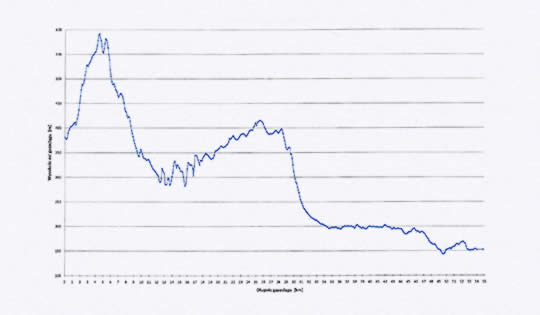
- performing of internal inspection of pipelines using intelligent pig MFL,
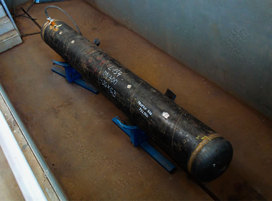
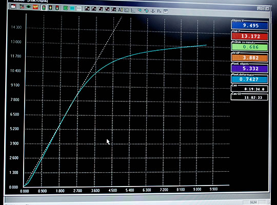
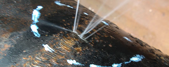
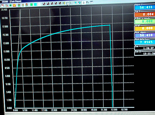
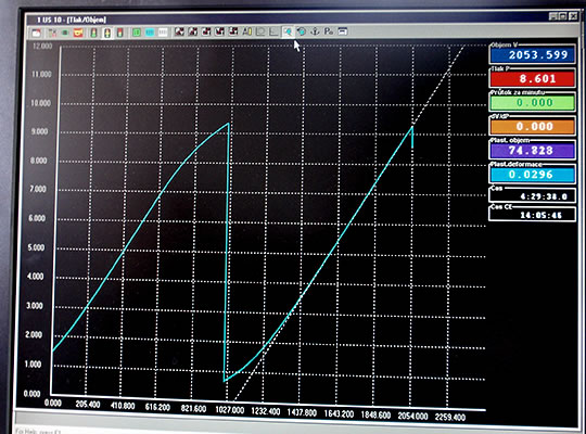
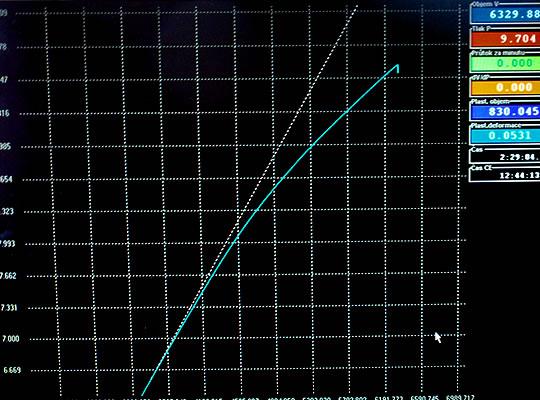
- testing of pipe material and pressure tests of the pipe body on the part of pipe cut from the pipeline and
- pressure reparation and drying of the pipe.
Basic data on pipeline
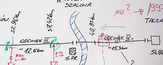
Pipeline DN 400 PN 55, which was mainly used to supply the area around Jelenia Gora by natural gas, was built in 1991–1992 and 1997 of screw welded pipes 406 × 6.3 mm made of steel 18G2A. On pipe bends, into protective sleeves and for crossings were used pipes 406 × 8.8 mm made of steel R45. From actual building of construction, however, only part of the inspection documents of pipe material for pipelines made of steel 18G2A was preserved, to the pipe made of steel R45 the documentation did not survive.
The pipeline was designed and built as a cleanable with the entry and exit chamber for launching and receiving cleaning pistons. From the pipeline there are leading out three branch pipelines DN 250, 150 and 100.
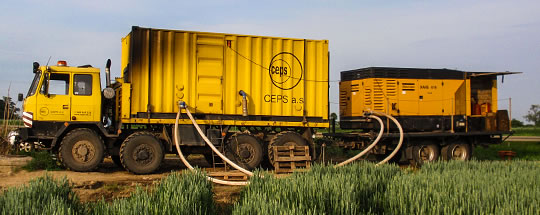
Pipeline cleaning and execution of internal pipeline inspection
This first phase was carried out by T. D. Williamson Polska. According to information from the operator the gas pipeline would never been cleaned; neither in operation and probably even nor during construction. Even if there was quite a considerable risk that the pig passing through the pipe stops in the column of impurities or at the deformed pipe, the operator required the cleaning during operation.
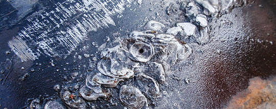
In the first process of cleaning the pig after about 40 km stuck at the point of crossing railway line. After the pipeline was excavated, on pipe was found sharp vertical segment bend, which hindered the passing of the pig. After cutting of this segment bending by using technology TDW STOPPLE, the pipeline was cleared for cleaning pistons and during the second cleaning the pig was picked up at the end of the pipeline in the receiving chamber. Afterwards it was made even multiple cleaning. In case of the first runs of the pig, the cleaning chamber at the end of the pipeline was half filled with dust.
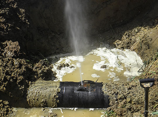
After cleaning the pipe on the gas pipeline there was performed internal inspection using a calibration and then intelligent pig MFL. By passing smart pig through gas pipeline there were detected many defects with a thinning pipe wall up to 79%. After the shutdown of the pipeline operation – before the start of pressure reparation – the largest of these defects were dug up and depending on the severity of found defects were either cut out or covered by the sleeve.