CEPS a.s. — Solutions that fit
home / services / about us / case studies / communications / contact / facebook
english / по-русски / česky / polski

case studies


On this page

  • The workflow in the process of reconstruction
  • Emptying of the section of pipeline DN 700 – preparatory creating of storage capacity
  • Preparation of sites for exchange of pipes
  • Emptying of oil pipeline DN 500 at the repaired section
  • Decontamination of pipeline DN 500 in section Pumping Station – pipe No. 974
  • The exchange of nonconforming pipes by cutting and inserting of new pipes
  • Checking of exchanged pipes by random
  • Time flow of carried out works
  • Benefits of new technology

Ordering partner

MERO ČR, a. s.

Pipeline

Druzhba oil pipeline, DN 700 + DN 500

Place of realization

Pump Station Klobouky–LVS Ořechov

State of realization

Czech Republic, EU

Date of realization

2007/09

Go to the related items

  • Services
  • Case studies
  • About us
  • Communications
  • Contacts

Exchange of 32 pipes on DN 500 crude oil pipeline within 88 hours – was that a world record?

In September 2007 the most extraordinary event was carried out it was unique both in its scope and in such a very short period during which it had to be implemented.

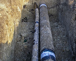
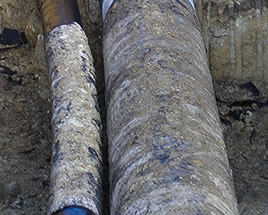
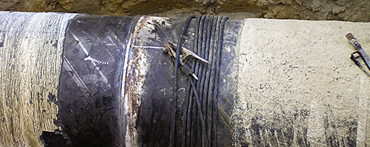
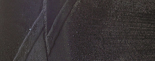
In the Czech part of crude oil pipeline Druzhba DN 500 in section in South Moravia the exchange of 32 pipes was accomplished that according to findings of an internal inspection by its parameters (wall thickness) did not meet the requirements for future safe operation of the pipeline.

These nonconforming pipes were irregularly deployed in two locations at approximately 8 km pipeline route near the pumping station; see Figure 1.

Diagram of crude oil pipeline route DN 500

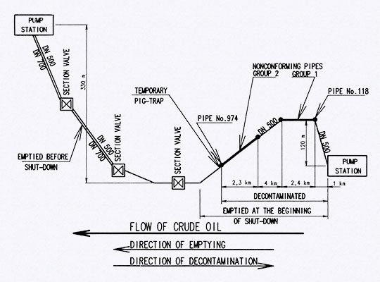
Figure 1 – Diagram of crude oil pipeline route DN 500

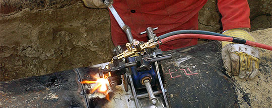
Exchange of pipes had to be made during regular technological pipeline shutdown lasting only 96 hours. Any extension of the length of shutdown would bring to the pipeline operator very high costs. This short period of implementation required an extremely large engagement of capacities for all types of work – displacement of crude oil from the pipeline, ensuring of safe environment for welding, assembly works during cuttings of unsatisfactory pipes and insertion of new ones into pipeline and NDT of made welds. It was therefore necessary to choose suitable services for the entire action, choose reliable suppliers of assembly works, technically and organizationally prepare in detail the whole event and then coordinate the activity of a large number of subcontractors on a relatively small area.

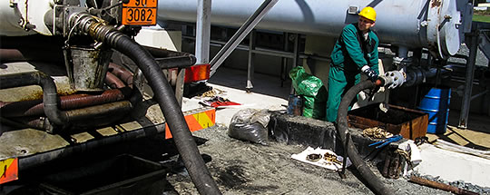
Before starting the exchange of pipes it was first of all necessary to displace oil from all pipes that being planned to be exchanged and then inside the pipeline to ensure a safe atmosphere for the implementation of open flame welding-assembly works.

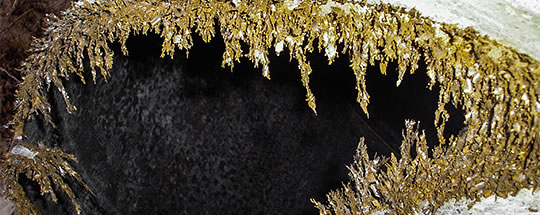
Implementation of these works individually on all sites at the same time is not realistic for time reasons, neither of availability of facilities for the temporary closure of pipelines, because it would be necessary to isolate 30 sites, which would mean using of 14 sets for temporary closure of the pipeline. Due to that an entirely new technology was chosen – crude oil was displaced from all destination of pipeline section with unsatisfactory pipes (section in length of 9.7 km) and after that the empty pipeline was decontaminated using a special technology, by that all the hydrocarbons were removed from the walls of the pipeline and so the safe environment for welding was ensured. After that cuttings of all failed pipes were realised and welding of new ones back were realised without any technological restrictions.

The oil pushed out of the pipe is normally transported to the nearest pumping station by road tankers or it is pumped from the closed section to the next section behind the section valve. However time for emptying was very limited. Removal of nearly 2,000 m³ of oil from the closed section by road tank trucks in disposable time was quite impossible. Even re-pumping of crude oil into another part of the pipeline at the same time was not easy – the technical equipments needed for pressuring (compressors with the pressure about 35 bar and necessary flow rate or powerful mobile pumps) are not in the Czech Republic and also probably elsewhere in Europe easily available. Therefore the more useful solution was found. In advance it was possible to empty the proper part of the parallel pipeline DN 700. Into this emptied section of the pipeline it was afterwards possible right at the beginning of the pipeline DN 500 shutdown quickly to push over the crude oil from the repaired section.


the workflow in the process of reconstruction

The workflow in the process of reconstruction

The workflow in the process of reconstruction of oil pipeline DN 500 was as follows:

  1. Preparatory works before the start of cut off
    1. Emptying of the section of pipeline DN 700 – creation of free “storage” capacity for rapid re-pumping of oil from the repaired section,
    2. Preparation of the working sites for pipe exchange (stake out of tubes to replace, earthworks, tracing and verifying of pipes for replacement, NDT of existing pipeline in the sections planned for cutting, distribution of new pipes to the places of exchange).
  2. After starting of the cut off
    1. Push out of oil from the pipeline DN 500 from the whole repaired section of nearly 11 km,
    2. Preparing the repaired part of pipeline for decontamination – cut out the last downstream nonconforming pipe and welding on temporary cleaning pig trap,
    3. Decontamination of oil pipeline DN 500 section between the pumping station of pipeline and the last nonconforming pipe (No. 974) for a 9.6 km,
    4. Exchange of 32 nonconforming pipes by cutting out and putting the new ones,
    5. NDT inspection of already made welds,
    6. Putting the pipeline into operation,
    7. Completion of the isolation points of the welds, filling of excavations and final completion of the ground.

As the section of pipe exchange was near a pipeline pumping station so was for pushing out the oil from the repaired section and its decontamination used stationary pig trap. In case that this chamber would not be close to the section so it would be necessary to separate the pipeline differently, for example by using technologies TDW STOPPLE.

Emptying of the section of pipeline DN 700 – preparatory creating of storage capacity

Emptying of the section of pipeline DN 700 was done in advance so that it would be possible to re-pump oil from the repaired section into this empty pipeline immediately after the beginning of shutdown of pipeline DN 500.

Displacement of oil into road tank trucks at the end of the pipeline DN 700

Figure 2 – Displacement of oil into road tank trucks at the end of the pipeline DN 700

The oil from the section of pipeline DN 700 was pushed away by multidisc bi-di pig driven by compressed air from a nearby section valve to the end of the pipeline where it was pumped into road tank trucks (see Figure 2). After that the oil was transported to neighbouring pumping stations where it was gradually pumped back across the balancing tank into the pipeline DN 500.

The transported amount of the oil from the section was about 2,450 m³. During emptying of pipeline for the time period of 5 days were used 8 road tank trucks with a capacity of 10 and 30 m³.

The pipeline DN 700 was during emptying by comprehensive ecological measures secured to prevent pollution of the environment by oil. All small leaks and incurred wastes were immediately ecologically disposed.

Preparation of sites for exchange of pipes

Nonconforming pipes were set out in advance on the basis of reports from internal inspections of pipelines and after stripping were traced and insulated pipe welds.

Subsequently it was examined whether stripped pipes are really the pipes specified for the exchange. First of all the length of pipe (weld distance) was measured. Then wall thicknesses of a pipe for exchange and also adjacent pipes were detected using ultrasonic and measured values were compared with reports of an internal inspection. The last check was to compare positions and distances of spiral circumferential welds on pipes adjacent to the state in the report.

Pipes for the exchange were subsequently stripped in full length and at a spot of a weld were made the excavations. During the uncovering of pipes it was found out that the parallel pipeline DN 200 is lead in several places in proximity of the pipeline DN 500 at a distance of only 10 cm, see Figure 3 and Figure 4.

Former position of pipes at the place of pipe No. 118

Figure 3 – Former position of pipes at the place of pipe No. 118

Former position of pipes at the place of pipe No. 118 (detail)

Figure 4 – Former position of pipes at the place of pipe No. 118 (detail)


On a repaired pipe there was selected a place for future welds of putting in pipes therefore checking of wall thicknesses of pipes in the future spots of welds for the presence of cracks and/or lamination by ultrasonic testing (UT) and magnetic particle testing (MT). For the welded pipes was furthermore assessed the quality of the production weld. The inspection found several undesirable defects (lamination and small surface cracks). Places with identified defects have been identified and the length of the pipe was part exchanged for them increased.

To the oil pipeline was during the operation installed 8 nipples TDW TOR 2″ which were subsequently used to identify the location of the pig and to check the state of the environment inside clean and decontaminated pipeline.

For replacement of nonconforming pipes were used new spiral-welded pipes, 530 × 8.00 mm, material L 360 MB, with asphalt isolation. Currently the unusual outer diameter of the pipe is given by the fact that the pipeline was built in the mid-sixties when in Czechoslovakia applicable standards stipulated this size as the standard one. New asphalt isolation of pipes was used on the basis of the analysis of corrosion. According to the opinion of experts it is suggested during reconstruction to use exactly the same system of isolation as at the surrounding pipes – the entire pipeline has the asphalt isolation (during the reconstruction it was interesting to find out that the original asphalt isolation is in a very good shape at the age of almost 50 years). Tubes for repair with this unique specification were delivered by Mittal Steel (now ArcelorMittal) Ostrava.

Delivery of new pipes to the sites was more difficult due to the state of terrain, which was at the time because of heavy rains in places impassable for wheeled vehicles.

Emptying of oil pipeline DN 500 at the repaired section

Emptying of the repaired section of pipe DN 500 was performed using a set of bi-di pigs. Between them was pumped defined amount of water that acted as an inertization stopper.

Preparation of final chamber inside the pumping station

Figure 5 – Preparation of final chamber inside the pumping station

Assembly of pigs and water plugs were inserted into a permanent end chamber of pipeline DN 500 in the area of pumping station. Assembly of pigs was pushed by compressed air inside the pipeline toward section closer behind the repaired section of pipe and in its movement was pushing oil out from the pipeline. Crude oil flowed by pipeline DN 500 to the section valves node where it was pushed by the interconnecting pipe DN 500 into already prepared empty section of the pipeline DN 700.

Pushing of compressed air into pipe for pushing away of oil

Figure 6 – Pushing of compressed air into pipe for pushing away of oil

Decontamination of pipeline DN 500 in section Pumping Station – pipe No. 974

After pushing away of oil from the repaired section of the pipeline up to 1 km beyond the last planned cutting (pipe No. 974); the cut out of unsatisfactory pipe was done by flameless way. The pipe was removed from the pipeline and secured against drops of oil residues.

It was stated that after cutting out of the pipe, the pipeline is reliably empty and that the oil film remaining on the inner surface of the pipe is very thin. However inside the pipeline there was still an explosive atmosphere not allowing working with open flame.

Both ends of the pipe were manually cleaned of oil residues. A separator pig PLP inserted into the pipe hermetically sealed continued pipe of oil pipeline at the split.

The clay seal was installed into the cut pipeline at the end of repaired section. After checking the safety of atmosphere, the special temporary cleaning pig trap fitted with cleaning pigs was welded on.

These works were carried out under the strict fire and ecological security. Any small leak and the developed wastes were immediately ecologically disposed.

Special surfactant PETROSOL was developed in recent years for decontamination of pipelines transporting crude oil and petroleum products. This cleaning agent was originally developed for the decontamination of pipelines that are to be put definitely out of operation. Its effectiveness must guarantee that even after the direct contact with groundwater inside pipeline, the water is not contaminated by hydrocarbons. Result of this development is a very active substance that in addition is after the application even including decontaminated content easily disposed by biodegradable way. For the first time this technology was used in 2000 for decontamination of abandoned crude oil pipeline DN 300 in the length of 74 km. After several decontamination jobs at smaller lengths of product lines it has been used in 2005/2006 at DN 150 rehabilitated product pipeline totally 82 km long. In 2006 this technology was applied with a great success for the decontamination of 12 km long section of pipeline DN 500 that was definitely put out of service after the construction of a new section in the re-routed destination.

For the first time it was this project where the idea appeared that larger scattered assembly-welding works during reconstruction of longer sections of pipeline transporting crude oil or petroleum products could be significantly speeded up by the decontamination of a line in the entire length thereby safe conditions for work with open flame everywhere in the entire length of pipeline are achieved.

This new technology was used for the first time during the reconditioning of pipeline at this action. Between the pigs inserted into a temporary cleaning chamber was gradually pumped in precisely specified quantity of decontaminant surfactant PETROSOL in several well-defined ranges of concentrations. The water stop was made as the last act. After that this set of pigs and cleaning plugs were pushed by compressed air under control to the pumping station. The speed of this cleaning set was determined by calculation of transfers of oil residues into the surfactants of PETROSOL having various concentrations.

Inner surface of the pipeline before decontamination

Figure 7 – Inner surface of the pipeline before decontamination

After arriving of the whole cleaning set into the pumping station, the used decontamination surfactant was pushed into road tank trucks and transported to ecological disposal using bioremediation way.

After pushing out of the decontamination surfactant the compressed air was removed from the pipeline whereas there was preliminarily measured the concentration of explosive gases coming outside from pipeline over 3 nipples TDW TOR 2″ that were for this purpose previously installed on the pipeline. After the de-pressurisation was completed, the concentration of explosive gases inside the pipeline through these nipples was measured again. It was verified by this measurement that the content of explosive gases in the pipeline is significantly below the lower explosion limits and therefore the oxyacetylene flame can be used for cut-outs.

All subsequently realised cut-outs confirmed, that the inner surface of the pipe is by decontamination completely free off any oil residues and that the surface was clean with no grease or oil deposits, see Figure 8.

Inner surface of the pipeline after decontamination

Figure 8 – Inner surface of the pipeline after decontamination

The exchange of nonconforming pipes by cutting and inserting of new pipes

Exchange of 32 pipes within 96 hours represented a great deal of work that involved large numbers of personnel and equipment. Between 19 and 20 September 2007 up to 100 workers from 14 cooperating companies directly participated in the work.

For cooperation in the process of pipes replacing Company CEPS, the main contractor, chose such partner companies that could prove the reasonable assurance, that they will make welding and assembly works in the required quality and within a very short period of time. CEPS selected only these partners whose quality of control system was certified according to ISO 9001, some of them were also holders of the certificate ISO 14001 (protection of the environment) and OHSAS 18001 (safety). All companies have a long experience with the implementation of construction-assembly work on the Druzhba oil pipeline or high-pressure gas pipelines and are certified in the system of company GAS for assembly work on high-pressure pipelines.

Totally 16 fully equipped working groups of individual contractors for assembly works were engaged. Intensity of setting of working groups is evident from Figure 9.

Engagement of four working groups during pipe exchange

Figure 9 – Engagement of four working groups during pipe exchange

The same demands for qualities of work were put on NDT works. For those works was chosen the company having the extensive experience in the field of NDT long distance pipelines and also certified according ISO 9001. There were engaged 8 working groups including 5 mobile RT laboratories.

Access to few sites, especially to the most working sites of section No. 1, was due to waterlogged terrain quite difficult. Four sites in section No. 2 were in a relatively steep ravine.

With regard to the fact that for all pipes (except pipe No. 974) decontamination of pipeline was ensured the explosion-proof and fireproof environment, so it was possible after cut-out of a pipeline to use flame which significantly speeded up the work.

Cut-outs of defective pipes were therefore carried out mainly by oxyacetylene flame; see Figure 10.

Cut-out by oxyacetylene flame

Figure 10 – Cut-out by oxyacetylene flame

Already during cut-outs of pipes it was found out that the pipeline was very strongly magnetized. The magnetic field intensity was so strong that even objects weighing as hammer sustained on the pipeline. The example of magnetization after cutting of pipeline is shown on a Figure 11. This strong magnetization significantly complicated welding and did not only prolong the welding period but also caused several defects in welds.

Magnetized pipe at the place of cutting

Figure 11 – Magnetized pipe at the place of cutting

Welding of new pipes was carried out in accordance with the requirements of EN 12732 – for welding supervision, according to WPS of individual assembly companies which were qualified through WPQR or WPAR.

During the welding process it was necessary to minimize the influence of strong magnetizing of pipe. Mainly using the second magnetic field created by wrapping loops of welding wires carried out the compensation; see Figure 12.

Compensation of magnetized pipes

Figure 12 – Compensation of magnetized pipes

There was a special case when welding on the pipe, replacing pipe No. 974 located at the end of the repaired section. There was impossible to ensure the explosion proof environment by decontamination of pipeline, as the pipe end of continuing pipeline was not a part of decontaminated line. At this end of continuing line inside the next pipe No. 975 the PLP sealing pig was inserted, closing the line during all the time of works. The replacing pipe was inserted as one of the last pipes. Using degreasing agent the free part of pipe No. 975 between the PLP pig and pipe’s end was manually cleaned. Prior to the start of works associated with welding on the pipe, safety of atmosphere for welding was verified and also the unchanged position of the PLP pig was checked. Temporary clay plug secured final tightness in front of the head of PLP. Inserting of the pipe was strictly fire and environmentally secured.

Insertion of the pipe that was the nearest to the pumping station (No. 118) was carried out the similar way.

The NDT controls were made after performing circumferential welds of inserted pipes as follows:

  • Visual control (VT) of the weld according to EN 970,
  • Magnetic control (MT) according to EN 1290,
  • Radiographic control (RT) according to EN 1435.

Few defects in welds were removed by grinding and subsequent repair according to the appropriate WPS. In all cases the defects were removed by the first revision.

Emptying and decontamination of the pipeline DN 500 and following welding-assembly works including NDT controls of the welds were completed in 87.5 hours after the commencement of shut-down. Since then it was possible to put the pipeline back into service.

After the finalization of pipe exchange, the empty part of the pipeline was gradually filled by crude oil pumped by operating pumps of pumping station at the beginning of the repaired section. Displaced air was blown through the nipple TDW TOR 2″ and road tank truck. After the displacement of air the normal operation of the pipeline started.

Checking of exchanged pipes by random

The condition of defective exchanged pipes was controlled by random. The following findings are probably valid for the large part of the Druzhba pipeline:

  • Quality of isolation is good, isolation is bonded,
  • No corrosion on the pipe was found,
  • Inner surface of pipes is good,
  • Spiral-welded pipes were in the original installation during the construction of the pipeline in several areas inappropriately assembled – in places of two joints of spiral welded pipes is a small weld distance (see Figure 13)
  • Quality of some circumferential welds does not fully respect the current standards.
Inappropriately assembled welded pipes

Figure 13 – Inappropriately assembled welded pipes


time flow of carried out works

Time flow of carried out works

All works were not only realized in the demanded interval of 96 hours but even they were managed in significantly shortcut duration of 87.5 hours of continuous works, during those it was made:

  • displacement of oil from almost 11 km of pipeline DN 500,
  • decontamination of 9.66 km of oil pipeline DN 500,
  • 32 cut-outs and insertion of pipes on pipeline DN 500 including NDT.
Time flow of all works during cut-off of the pipeline
September 17, 2007 at 6:00 beginning of pipeline cut-off and start of pushing out the oil
at 9:00 oil pushed out behind the place of last cut-out
at 9:45 displacement of approximately 2,400 m³ of oil was finished, discharges of compressed air initiated
at 12:00 the discharge of air was completed
from 12:00 to19:00 made the cut-out of pipe No. 974 was made, temporary cleaning chamber welded
from 19:00 to 23:00 into the pipeline is pumped the decontamination surfactant PETROSOL
from 23:00 to 10:30 the following day the decontamination of pipeline DN 500 in length of 9.7 km was carried out
September 18 from 10:30 to 17:45 cleaning agent PETROSOL used for decontamination pumped from a pipe into road tank trucks and transported for the ecological disposal
from 17:45 to 18:30 depressurising of decontaminated section of pipe DN 500
at 18:30 checking of a safe environment in the pipeline and initializing of first cut-out of a pipe by oxyacetylene flame
at 20:00 other 5 cut-outs of a pipeline were made
September 19 at 20:00 all 32 pipes determined for exchange were cut out, insertion of new 16 pipes finished
September 20 at 21:30 NDT control of the last inserted pipe completed – it was possible to start the full operation of the pipeline after 87.5 hours of works

benefits of new technology

Benefits of new technology

Newly applied technology allowed exchanging at the pipeline the large number of pipes deployed irregularly along the route in a short time limit of the cut off. Displacement of oil from the pipeline and the subsequent decontamination of the pipeline prepared conditions for its own exchange.

The traditional way – the closure by the technology STOPPLE and removal of oil by road tank trucks, closing of pipeline at the place of cutting by the viewports clay stoppers or seals and pigs ensure a safe atmosphere by manual cleaning – in the given limit did not allow at all. In addition to that the large number of clay plugs that would be pushed out after putting into the pumping station. It could cause damage to certain parts of the station.

Another indisputable positive is the economic advantage.

The above mentioned findings justified the use of this technology in actions of a similar character given by the large volume of welding-assembly works in the short term for the long distance flammable liquid pipelines.

In the next two years this technology has been used already several times, both on the pipelines of oil and pipeline for transporting oil derivatives. The total length of decontaminated pipelines has already exceeded 400 km only in the Czech Republic.


related services

The following services were provided with this project

  • All services

Pigging services – mechanical and chemical cleaning

Nitrogen services

services


related case studies

See related CEPS case studies

  • All case studies

Comprehensive approach to the decommissioning of oil pipelines

Lithuania, Latvia, Belarus, Slovakia, Czech Republic
2001–2016

case studies


related documents

For more documents and other information, see the section about us

  • All about CEPS

Technical specifications CZ

about CEPS


related communications

Read articles related to this case study

  • All articles

Replacing 32 pipes on the Druzhba oil pipeline in under 88 hours

PIPELINES International 3 / 2011

communications


contact

If you have any questions, do not hesitate to contact CEPS responsible persons

  • Contact us

Aleš Brynych

general manager – CEO

phone +420 241 021 547

info@ceps-as.cz

Filip Tesař

sales manager

phone +420 606 641 328

info@ceps-as.cz

CEPS a.s. Head office

phone +420 241 021 511
fax +420 241 021 512

e-mail info@ceps-as.cz

see all contacts and maps


© 2013–2025 CEPS a.s. / Technical specifications CZ / Contacts